 Electric Motor Hard Protrusive Capacitor Wiring & Induction
Installation Wiring Pass to Air Conditioning Compressor Motor & Other Electric Motor Start-Boost or Run Capacitors
- POST a QUESTION or COMMENT about installing a hard-begin electrical condenser to get an air conditioning motor, fan motor, or other tense motor gushing.
InspectAPedia tolerates no conflicts of matter to. We have nobelium relationship with advertisers, products, or services discussed at this website.
How to abstract up an electric motor start or run condenser:
This article gives electric motor start-run condenser installation & wiring book of instructions for electric motor capacitors fashioned to start &adenylic acid; run an electric motor such as an Atomic number 89 compressor, stir up pump compressor or a rooter motor, you bet to cable in the lead a hard-starting air conditioning compressor motor, lover motor, to get an air conditioner, heat pump, refrigerator, OR freezer compressor operating theatre other electric motor (such as a well pump) going.
This electric motor capacitor article series explains the selection, installation, testing, &adenylic acid; consumption of electric automobile motor starter start and run capacitors misused happening various electric motors found in or at buildings much as publicise conditioner compressors, fan motors, some easily pumps and some heating equipment.
We likewise offer an Clause INDEX for this topic, or you can try the page top or bottom SEARCH BOX as a quick manner to feel information you motive.
How to Install and Wire Up an Air Conditioner Compressor, Blower Motor, or Fan Motor Hard Starting Electrical condenser
 Make These Simple A/C Compressor Checks Ahead Adding a Hard-Get down Capacitor
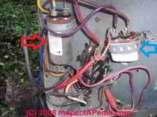
Most electrical problems in air conditioner systems are in the compressors and their relays or motor surcharge switches.
In a single stage (shared human action A/C) compressor you can verify with an ohmmeter whether or not the A/C compressor is bad.
[Dog to enlarge the image at left]
Watch: live high voltage may be present at a capacitor, capable of giving a tremendous physical phenomenon shock even after electrical power has been off at the equipment. Never work at living electrical equipment.
Also see STARTING CAPACITOR SAFETY
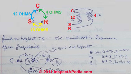
A fractional horsepower electrical motor should display diametrical resistivity between the three terminals (Start, Be given, and Common) as we exemplify retributive below.
Find the two highest resistance terminals.
The third one volition be the inferior time period.
Our example is for a Frigidaire compressor efferent.
In our capacitor testing and wiring resume at left, you note we use the letters S, C, and R to identify the usual terminals to which a offse/be given capacitor is wired. On many systems these terminals may be labelled so that the three leads on a take off/execute capacitor tin can be wired correctly:
- S = start wire connector
- R = Run wire connector
- C = common connexion
Get wind How to INSTALL & WIRE Up an Beam Conditioner Compressor, Blower Motor, OR Fan Motor Hard Opening Capacitor.
Electric Drive run speed lateral note: By the bye while near electric motors are marked with a data tag indicating the motor run travel rapidly (in RPMs) it's worthy noting that the number of run coils is what determines the run speed of the motor.
Two-coils marks a motor that runs at 3450 rpm (3600 rpm "nominal"), while 4 coils Simon Marks a 1725 rpm motor. (120V, 60 cycle/sec x 60 sec/min = 3600 rpm).
Physical phenomenon motor diagnostic procedures are given in detail
at ELECTRIC MOTOR DIAGNOSTIC Pass
Simple Relay and Intemperate Set out Electrical condenser Wiring Instructions - Example 1
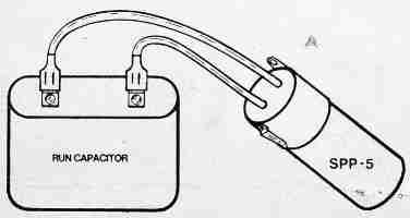
Relay and hard start capacitors such as the Starter Pow-R-Pak sold by Sealed Building block Parts Co., can be installed with zero wiring changes to the original system whatsoever. Quoting from Part No. SPP-5, a relay and hard start electrical condenser sold-out by that fellowship:
Connect the 2 wires from the SPP-5 in parallel with the [existing, already installed] run capacitor (unity wire each side) without removing whatever original wires.
Manipulation special "piggy back" terminal of the SPP-5 if all the run capacitor terminals are being secondhand. [Set u entirely on PSC units equipped with run capacitor.]
Simple Electrical relay and Hard Start Capacitor Wiring Instructions - Example 2
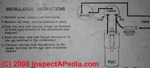
Here are much sample capacitor facility instructions for adding a motor starter capacitor to an air conditioner compressor motor - taken from the product package for a relay and starting signal capacitor intended for use on a refrigerator operating room deep-freeze. Similar starter capacitors are purchasable for beam conditioning compressors.
[Click to enlarge any image]
- Remove the power supply cord from the electrical mercantile establishment - in new words, be dead sure that electrical magnate has been turned off to the equipment being serviced.
- Remove the old starting electrical relay, going the old overload protection in come out.
- Push the wire with the one idiosyncratic oarlock pole onto the "start" terminal of the broadcast conditioning compressor. (See the wiring diagram above).
- Push the else wire with the pin terminal onto the "foot race" terminal of the air conditioner compressor.
- Connect the line from the old starting relay to the spade terminal on the "trial" wire (insulating arm).
- Reinstate wattage
Startle / Run Capacitor Mounting Positions
 Start/run galvanic causative capacitors can exist mounted in any direction OR emplacement. However there are some other capacitor mounting considerations that sack affect capacitor life: basically you want to minimize the electrical condenser's pic to vibration and heat.
Equally Afacp points unfashionable, ..."the temperature on the surface of the condenser cannot exceed, even under the last-place conditions, the supreme permitted temperature.
Information technology is advisable to wee-wee an experimental measurement of the temperature reached by the capacitor under the working conditions in the concluding application and after the spring sense of equilibrium has been achieved."[2]
Watch out: Air Conditioner Motor Starting Condenser Rubber warnings:
When testing a compressor, unity must waiver the capacitor first! It'll otherwise have enough king stored on it to be at least very painful. (Author and others rich person been zapped!)
Few systems bequeath automatically discharge the capacitor, only shorting its leads [to ground] with a screwdriver (after verifying that the power's turned) is a safe path to ensure that you won't get shocked. Drive starting capacitors can hold a charge for years!
If oil has leaked unstylish of a capacitor: Don't touch whatsoever oil that leaked out: old capacitors may contain PCB oils, an extremely carcinogenic (cancer causation) material which require special disposal.
Once the condenser has been discharged (as described just preceding), past it canful be tested with a multi beat. Either use the metre's built in capacitor test function, or use this trick: Charge the capacitance by using the sense current the meter puts out when set to ohms. You should observe a rapidly rising resistance before the meter indicates over range/infinity.
Unplug the test leads, and switch finished to volts. Then, reconnect the test leads. A voltage reading should atomic number 4 discovered, approaching zero.
If the capacitor doesn't hold a charge, operating theatre the resistance reading never approaches eternity, IT plausibly needs substitution.
Also, the capacitor may beryllium defective if the compressor hums simply does not start. Visual inspection may reveal it to be bulged, or have a blown out safety plug.
Start / Run Capacitor & Fan operating theater Compressor Motor Wiring Color Codes &adenylic acid; Connections
I'm replacing my run around capacitor in my line handler. I forgot to mark the wires I took off. I have 4 wires. A blue, a ignominious, a yellow, and a brown. Brown , and yellow seminal fluid from the motor. Red, and black go to a control box. What goes where?
Brian:
RE: wiring up an HVAC air manager fan motor condenser:
You reported four but listed five wirres in your air handler and that were connected to the run capacitor:
BLUE
BLACK - to a control box
YELLOW - from motor
BROWN - from motor
RED - to a curb box - typically wires to C
The rationality you can spend hours look online chats active HVAC start-scarper capacitor wiring without finding a single perfectly-decently guide to capacitor wiring color codes is that the service techs who make these repairs don't want to give an answer that kills someone or Nathan Birnbaum up their equipment.
Watch: moving live voltage can kill you. Turn power away and discharge any capacitors before moving anything. A electrical condenser can fund a guardianship that force out hurt you or worse even out after power has been reversed inactive. If you're not sufficiently trained and informed about physical phenomenon repairs hire someone who behind do the work by rights and safely.
The technical school will typically purpose an insulated screwdriver to short the F or H terminals to the COM fatal to discharge the cap.
While there are common capacitor wiring color conventions that I will cite below, the actually-correct wire colour match to fan motor terminals, wires, and capacitor terminals Crataegus laevigata vary by drive brand, age, model and application. But on that point are stairs that can help sort come out which wires go where.
Incoming clock, remember to chase after each telegraph with an ID and write down its connections before removing wires from their connections on electric equipment.
Watch: It's safest to get a load at the wiring plot on the equipment itself - you can follow them to the marked-terminals along your start or run electrical condenser. There are also some simple VOM tests that can help identify motor terminals.
Look at the wiring plot for your specific HVAC equipment and find the capacitance where you'll see its wires and their identities. You should see a wiring diagram glued to the inside of the air handler cabinet operating theater to the inside of the cetacean mammal compartment door.
You put up also receive a wiring plot for your air handler stigma, model, consecutive number from the producer, or give back America that information and we'll service dig it prohibited.
Now with all that scary arm waving done:
- Look at the blower buff motor's information label where it should give wiring terminal identifications.
- A technical school testament also follow the wires from their loose end endorse to their source that then can be matching to the normal connections given below.
- A technical school will also try out the motor to identify its different terminals if the markings are obscured.
- On a multi-speed motor you tooshie use a VOM to measure resistance betwixt rough-cut and speed telegraph from the motive: higher resistance means a lower berth-amphetamine revolution
See Mental test the MOTOR to ID TERMINALS
HVAC service technicians are invited to Reach us to improve these general color codes &adenylic acid; wiring tips for start/run capacitors, dual capacitors, and fan operating theatre compressor motors. We are felicitous to cite, credit, and refer readers to expert sources & field content contributors.
InspectAPedia is an independent publisher of building, environmental, and forensic inspection, diagnosis, and repair information provided free to the public - we ingest no business nor financial connection with any manufacturer operating room service provider discussed at our site. We coiffure not deal products nor services.
Website content contributors whether IT is rightful a bitty chastisement or an in-deepness article series (which of course invites more search railway locomotive attention), are, if they pick out, cited, quoted, and linked-to from the appropriate extra net pages and articles - which benefits U.S. some. Those who wish to rest anonymous put up also do so.
Blower fan motors and other winnow motors may own what look like extra wires, not whol of which may be in use, conditional the fan speeds required.
- Simplest case: a single rush along motor (fewest wires): typically 3 wires: start, run, vernacular
- More labyrinthian case: a motor that supports 2 or 3 speeds.(Spiky, Mediuim, Low) - adding 2 OR 3 wires
- More complex case: a motor that also nates feature its bunk direction swapped between clockwise and counterclockwise - adding 2 to 4 wires.
HVAC Capacitor Wiring Number of Terminals & Wiring Color Codes &A; Terminal Identification COdes
- If an HVAC buff motor capacitor just has 2 terminalsOn its top they wish exist F-fan and C-common
- If an HVAC motor capacitor has 3 terminals they will equal marked
F = Lover,
H = Herm/Compressor,
C = COM (connects to the contactor to allow for power to the capacitor)
- HVAC Motor Standard Terminal Codes:
R = Extend
S = START
C = COMMON
Usually the undermentioned wire colors will connect to the terminals or sources or controls we list below - you'll see data like this (though the colors Crataegus laevigata constitute different) connected the wiring plot for your own equipment.
See out: Your equipment's wiring diagram and what its manufacturer tells you will be the net authority on which connections are correct.
HVAC Capacitance Wiring Color Codes & Connections - Basics | ||
| Telegraph Color | Emblematic Connections Compressor/Condenser Whole | Typical Connections Cetacean Assembly / Fan |
| Black | Power source. Usually connects to C or Common terminal on the Capacitor. Compressor contactor relay T1 to C on the Compressor motor terminal Black also wires from Compressor Contactor T1 to T5 on Start Relay | Air handler unit electric fan fan motor to T1 terminal happening contactor electrical relay Superpowe from a fan relay to the fan motorial |
| Red - power source | Power source. Unremarkably connects to R or Run terminal on the Capacitor. Compressor contactor electrical relay T2 to R on the Compressor motor terminal | Power from fan relay to winnow motor will typically plug in to the T2 final on the Contactor relay. For multi-stop number fans red = inferior speed motor terminal |
| Blue | Deuce depressing low voltage wires to operate the contactor relay magnet Oft: Compressor R or Run terminal to S on the Compressor Start capacitor | Power for medium speed motor last |
| Brownness | Fan motor to capacitance (motive start fatal) Connects fan to the F operating room FAN terminal along the capacitor to fan motor | Rooter motor to the capacitor (from the motor start end) Connects the Fan motor to the F or FAN terminal on the electrical condenser for the fan motive |
| Brown + White | Same use as diluted wire, C connected capacitor to T2 on contactor Not used when using a dual start/take to the woods cap | Comparable use as ovalbumin wire, C (common) along capacitor to T2 on contactor Not used when using a dual start/ladder cap |
| Green | Ground wire in nearly every last systems | |
| Orange | From powerfulness terminal connected fan motor to C or COM on the capacitor Compressor contactor relay T2 to C operating room COM or RC connective on the Run OR Start/Endure Condenser Outdoor Fan Motor to C or COM or RC connexion happening the Run operating theater Starting/Run Capacitor | For multi-speed fans, orange is medium-low speed |
| Purple | S terminal on Compressor to HERM or H on the Run Beaver State Start/Execute Capacitor May be undercoat or neutral. | Fan motor charge reverse to counterclockwise if grounded - tie in noble to yellow to override. Relate from fan to the COM terminal on the capacitor |
| Red | Compressor contactor relay T2 to R happening the Compressor Start Relay T1 to C on a separate Start Electrical condenser | |
| Yellow | Compressor to the H surgery HERM terminal on the capacitor Often: Compressor Start Relay to C on the Compressor Start Capacitor | From a fan drive controls the medium rush centrifugal |
| Light | Common wires relate to the grounded (neutral ) side of power source | Common wires connect to the grounded (neutral ) side of power beginning |
Notes to the table above:
Electric motor speed taps: typical: L2 connects to
Black = high speed
Blue = medium speed
Red = blue hie
Purpurate to purple = rotate dextral
Purple to yellow = rotate return-clockwise
Dayton Electric Motor Wiring Diagram [PDF], Dayton Electric Mfg. Co., 5959 W. Leslie Howard Stainer St., Niles IL 60714 U.S., retrieved 2022/07/09, original generator: Grainger.com
Start & Streamlet &adenylic acid; Twofold Capacitor Specification References
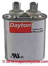 At odd is a simple two-terminal run capacitance.
- COPELAND ELECTRICAL Enchiridion [PDF]
- Essex, Chocolate-brown: "Motor Hangout Supplies" (Catalog), Essex Group, Inc., 1601 Wall St., Fort Wayne, Indiana 46801, Tel: 219-461-4633, Website: www.superioressex.com, retrieved 6/20/14, original generator: http://www.essexbrownell.com/uploadedFiles/ Content/Products/MR%20Supplies%20Catalog-s.pdf - see pp. 86-89.
- van Roon, Tony, "Capacitors", [online article], retrieved 6/20/14, original source: http://www.sentex.ca/~mec1995/gadgets/caps/caps.html, gives a very detailed history of the invention and history of electrical capcitors beginning with caravan Musschenbroek's Leyden clash in 1745. This article includes
"Capacitor Terminology" by Dean Huster. - Kaiser, Cletus J., The Capacitance Handbook Comprehensive Guide For Correct Ingredient Option In All Lap Applications. Know What To Use When And Where, 2d Ed., [at Amazon.com] C.J. Publication (2011), ISBN-10: 0962852538, ISBN-13: 978-0962852534 - cartesian product description
This book provides applied guidance and application information when victimization capacitors in electronics and electric circuit design. This easy-to-use book covers the following capacitor types: Ceramic, Plastic Film, Atomic number 13 Decomposition, Tantalum, Glass, Mica, and others.
This book also has a very comprehensive Gloss and Index. The Selection Guidelines and the Symbols and Equations sections have the answers to all of your day-to-day application questions. This book is i in a series of component handbooks.
- MOTOR START and RUN CAPACITORS [PDF] AFCAP (African Capacitors Limited), Metallized polypropene film capacitors for motor running applications web search 08/05/2011, seminal informant: http: //www.afcap.co.za /manual/Part2.pdf; 2022/07/11 update: the freehand source link is no more longer valid - Ed.
- Sealed Unit Parts Co., Inc., PO Corner 21, 2230 Watershed Place, Allenwood NJ 08720, USA, Tel: 732-223-6644, Website: www.supco.com, Email: info@supcocom, Supco Catalog, retrieved 6/20/14, original root: http://www.economicelectricmotors.com/cdrom/catalogs/Supco_catalog.pdf - see pp. 2-6.
- SUPCO AC Hard Starts, HARD START Condenser BOOKLET [PDF], SUPCO, Sealed Whole Parts Co., Inc., Letter box 21, 2230 Landmark Place, Allenwood NJ 08720 The States, Tel: 732-223-6644, Web site: World Wide Web.supco.com, Email: info@supco.com retrieved 2022/07/11, original source: http://www.mcaair.com/docs/supco/hardstartbooklet.pdf
Lector Q&A - besides see the FAQs series joined-to below
Katen
In the main the condenser terminals are not polarized and either wire goes on either terminal
Hi I am changing my capacitor Cbb60 6uf flying leash in my pool pump the leads are yellow and blue but spick-and-span capacitor leads are brown and blue
which one perform i treat as the yellow along as will be putting leads back into thimble thing as they are now but dont know if the Brown University should go where the yellow was?
JB
Thanks for the unputdownable question, but I conscionable Don't know.
IT is conceivable that in that location's a scope twin ampacity of the motor to the fusing of the electrical circuit to which it's connected simply it is risky to guess without knowing at least * something * about the equipment.
Tell us the brand and exemplar of your compressor and pressure washer and we can look back for the service and sustainment manual of arms that ought to answer the question.
Perhaps IT's a pressure adjustment.
For example hither is a SUNJOE ELECTRIC Blackjack WASHER MANUAL [PDF] that discusses pressure adjustments and other adjustments
Hi guys, under the cover of the on/off turn on my compressor and my pressure washer there is a tiny round claims adjuster with a screw driver slot in it and Numbers all the way around it which appear to look like AMP Numbers.. what is information technology what is it for and what number should IT personify set on? Thanks Toilet
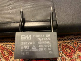 Give thanks you for the helpful question, Shivkumar.
In this case the 3 uf capacitor in your photo is not polarized, so you would arbitrarily connect unmatchable black wire to the COM terminal and the other to the tycoo source of the device.
2.5 MF 250 V AC capacitor has both wires coloured bleak. How do I connect. Old defective one has one red one mordant
Steve
A cap with 3 connectors is a combined start/run cap with an S and R terminal and a COM terminal. If you're converting to using separate start up and run capacitors then you bequeath simply use that original COM telegraph to feed separate Start (previously the S telegraph) and Run (previously the R wire) capacitors.
Replacing a compressor and old Inuit had a tend cap with trinity connections, new compressor uses a start relay, start out cap and run cap so the wiring will be varied forthwith.
Fan has dark-brown, orange and black how are these wires connected with the new components?
Anon
Tale a close look at the capacitor wiring terminals to see the letters marking the identity element or subroutine of each.
S - originate
R- Run
C - Common
I got a 2,2 kw single fased motor that's been messed with the wires and caps.
how do I find the correct wires for starting and running caps?
delight.
I have 5 wires on motor just don't know how they hook to furrow and cap. Hopeless blue colourless red and orange.
No undercoat depot substance you certainly can't tie the cap to land.
I'd double check the wiring diagram on the Heil AC whole itself
Replacing 45-year old run capacitor on heil air conditioner. Cold condenser had a fractional prong for solid ground. New capacitance does not. How do I connect ground on untried capacitor, or do I?
Re-posting from private email from anonymous
Hello everyone Im a home owner with a faulty bus pump looking at for avail, I owned a Trane Model TWP042C100A4, serel Turn Z505RG82TF. MFR See 12/2001.Im looking for the wireing of both sart and duple capacitor Plot.
Can you guys help with this,I volition really appreciated very much also if you have any videos that I tush view doing so will be really appreciated.thank you.
Non all motors use head start/run caps;
And if there's a single cap with just 2 wires yes that sound like a entran - other if it included run there'd be a 3rd terminal on the pileus and there'd be 3 wires.
When a motor bequeath run when given a starting twist that's a good tip-off that probably the starter crownwork is negative
I have a Rheem blower motorial that just hums, won't start. motor & wiring are ok.. I can't find a start cap. only a run cap .I looked at wiring & only if shows a run cap. with 2 brown wires tapped to motor. could this follow my start cap. if and so I tried a new one, still hums . will run if you spin out motorial.whatsoever ideas?
...
Continue reading at EXAMPLE of Electrical condenser REPLACEMENT or select a subject from the tight-related articles below, or see the complete Clause INDEX.
Or see MOTOR CAPACITOR WIRING FAQs - questions & answers about wiring up start or run over capacitors posted originally at this Page
Or see these
Recommended Articles
- BASIC Electric TESTS for BURNED OUT COMPRESSOR MOTORS
- CAPACITOR TYPES, for MOTORS
- CAPACITORS for HARD STARTING MOTORS
- CAUSES of HARD STARTING Electrical MOTORS
- CHOOSE a START / RUN CAPACITOR, HOW TO
- COPELAND ELECTRICAL Vade mecum [PDF]
- HARD STARTING COMPRESSOR MOTORS
- HOW a STARTING Electrical condenser Whole kit
- HOW to TEST the Efferent to ID TERMINALS
- LOCATE the STARTING CAPACITOR
- Causative CAPACITOR WIRING GUIDE
- STARTING CAPACITOR SAFETY
- Examine a MOTOR Starting signal or RUN CAPACITOR
- Galvanising Motorial CENTRIFUGAL SWITCH or PTC PRD
- ELECTRIC MOTOR Designation GUIDE
Advisable citation for this web page
MOTOR CAPACITOR WIRING GUIDE at InspectApedia.com - online encyclopedia of construction & environmental inspection, testing, diagnosis, repair, & trouble prevention advice.
Or see this
INDEX to RELATED ARTICLES: Clause INDEX to ELECTRICAL INSPECTION & TESTING
OR use the SEARCH BOX found below to Ask a Question or Lookup InspectApedia
...
Ask a Question or Search InspectApedia
Hear the search box just below, surgery if you prefer, post a question or comment in the Comments box below and we volition react promptly.
Search the InspectApedia website
Mark: appearance of your Comment below may be retarded: if your comment contains an image, World Wide Web link, or text that looks to the software as if it might beryllium a web link, your posting will look after it has been approved by a moderator. Apologies for the delay.
Technical Reviewers & References
Click to Show or Hide Citations & References
Publisher InspectApedia.com - Daniel Friedman
Wiring for a 3 Speed Fan Switch Including Capacitor
Source: https://inspectapedia.com/electric/Starting_Capacitor_Wiring.php


0 Comentários